
PCB board platform
Board material, copper, surface finish and compact layout create the electronic base for the wearable device.
For teams searching for a pet tracking device manufacturer, Vortixion’s pet tracker PCB board clarifies the electronics platform behind the device. The page is useful when a custom pcb board manufacturer must support FR4 layout, antenna needs, battery charging and PCBA scale-up.
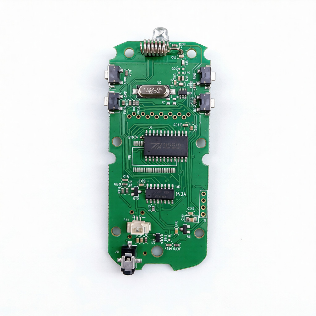
A pet tracker project contains more than one responsibility. Keep the PCB and PCBA scope clear before assigning enclosure, app, service and finished-device work.
Board material, copper, surface finish and compact layout create the electronic base for the wearable device.
Component mounting, battery charging circuitry and assembly planning turn the bare board into a functional hardware module.
Industrial design, app service, carrier plan, retail packaging and customer support need a separate project owner.
The useful conversation is not only board size. GPS, cellular, battery and sealing decisions all affect whether the pet wearable can move from prototype to production.
| Board format | Compact pet tracker PCB board assembly for wearable tracking hardware projects. |
|---|---|
| Base construction | FR4 material, 2L stack, 1.0 mm board thickness, 1 oz copper and HASL process. |
| Wireless needs | GPS and cellular antennas require space, RF routing awareness, matching decisions and validation planning. |
| Power and charging | Li-ion battery support and charging circuitry should be discussed with the target runtime and enclosure size. |
| Outdoor protection | Waterproof sealing and compact assembly constraints should be included in the hardware brief. |
The board can support a pet wearable project, but wording should stay specific: PCB/PCBA manufacturing support is different from a finished tracking-device service.
Use this order to keep the manufacturing conversation precise as the project moves from board design to assembled wearable electronics.
Define FR4 stack, layer count, copper and finish before mounted parts enter the build.
Place components around the BOM, board space, test points and expected assembly method.
Discuss GPS, cellular, charging and waterproof enclosure constraints together, not as isolated notes.
Separate prototype review from higher-volume assembly so yield, inspection and responsibility stay clear.
Send enough engineering context for a quote that matches the board, antenna environment and assembly route.
Layer count, material and thickness target.
GPS, cellular and enclosure constraints.
Battery, charging circuit and runtime goal.
Outdoor exposure and waterproof approach.
Confirmed components or open selections.
Prototype, pilot run or volume assembly.
Compare the pet tracker board with nearby PCB options when the project needs a different board format or application focus.

For projects that need fabricated boards before component mounting or PCBA responsibility is assigned.
View bare PCB board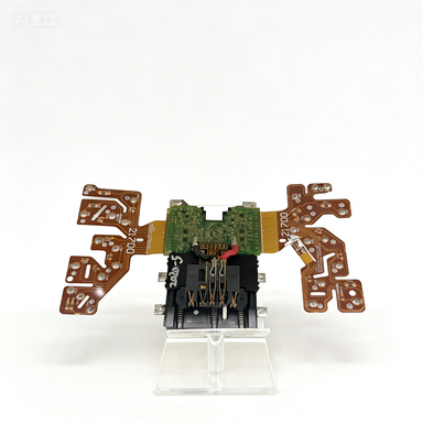
For compact designs where bendability and routing space matter more than a rigid board format.
View flex PCB board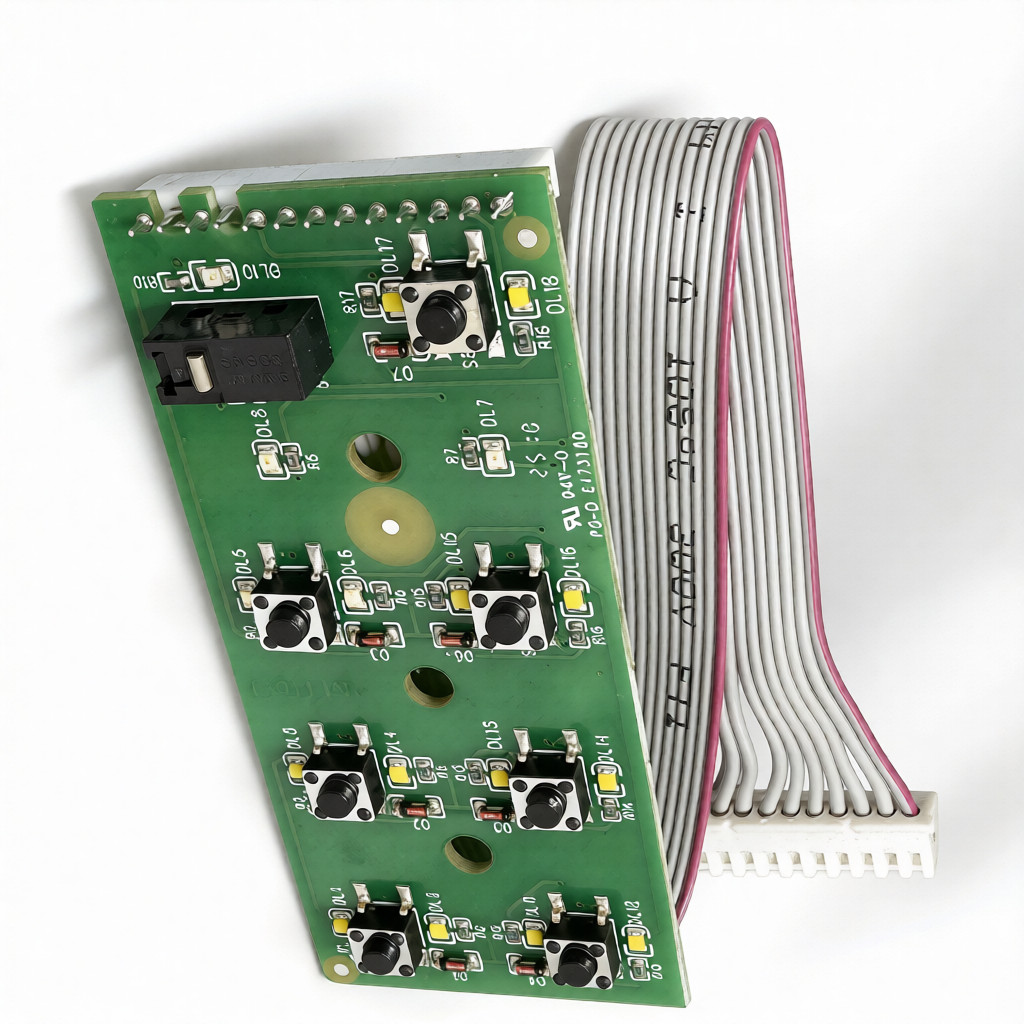
For an assembled control-board example outside pet wearables, useful when the application brief is appliance-focused.
View coffee maker PCBThese three notes help clarify service wording, antenna integration and device-level responsibility before a PCB project is quoted.
Use the terms carefully so the quote covers the correct manufacturing step.
Open service-term noteBring RF space, grounding and validation into the PCB discussion before the board is fixed.
Open antenna noteKeep PCB assembly responsibilities distinct from the finished wearable device business.
Open role noteSix focused answers for teams planning PCB manufacturing for pet tracker hardware.
The board is presented as a compact 2L FR4 PCB assembly for pet tracker projects, with GPS and cellular antenna needs, Li-ion battery charging, low-power design, and waterproof enclosure planning in scope.
This page focuses on the PCB and PCBA manufacturing layer. Finished-device ownership, enclosure branding, mobile apps, carrier plans, and end-user service promises need to be defined separately by the project owner.
Start with the FR4 material, 2L stack, 1.0 mm board thickness, 1 oz copper, HASL finish, antenna space, battery charging circuit, power target, and sealing expectations.
Wireless performance depends on layout, grounding, matching, enclosure space, and validation, so antenna needs should be discussed before the PCB moves from prototype to volume assembly.
Send the target device size, stack-up expectations, antenna requirements, battery and charging needs, sealing requirements, BOM status, prototype quantity, and volume assembly expectations.
Use bare PCB or flex PCB options when the project needs a different board format, and use another assembled-board example when the application is not a pet wearable.
