

Control Board for Inverter
Co-development of Inverter Control BoardOur team has spent six months cooperating closely with our valued client to jointly develop a brand-new inverter control board. We encounter
View productChoosing the input is the first real decision on a temperature controller board: a thermocouple reacts quickly across wide temperature ranges, while an RTD holds a steadier reading at lower setpoints. A complete industrial temperature controller board also has to pair an output stage with your load, a supply rail with your cabinet, and a channel count with the number of loops you run — so this page works through sensor, output, control, power and channel choices in the order engineers actually make them.

Each step narrows the next one. Start at the sensor, finish at the quote — and use these jumps to work through the page at your own pace.
The board accepts thermocouples, RTDs, analog voltage and analog current inputs. Measurement accuracy is stated as ±(0.2% of reading + 1 °C) or better depending on sensor type, with 0.1 °C / 0.1 °F input resolution across the range.
| Sensor family | Options on this board | Choose this if | Accuracy & resolution |
|---|---|---|---|
| Thermocouple | Types J, K, T, E, N, R, S, B | You run high-temperature processes, need a fast response, or already have thermocouple probes fitted to the machine. | ±(0.2% of reading + 1 °C) or better, depending on sensor type; 0.1 °C / 0.1 °F resolution |
| RTD | Pt100, Pt1000 — 2-wire, 3-wire, 4-wire | You need stable, repeatable control at low to mid temperatures, or you want to reduce lead-resistance error with a 3-wire or 4-wire hook-up. | ±(0.2% of reading + 1 °C) or better, depending on sensor type; 0.1 °C / 0.1 °F resolution |
| Analog voltage | 0–5 V, 0–10 V | An existing transmitter, PLC or instrument already delivers a voltage signal you want to read directly. | Consistent with the stated board accuracy; 0.1 °C / 0.1 °F resolution |
| Analog current | 4–20 mA, 0–20 mA | Cable runs are long, the environment is electrically noisy, or your loop follows a standard process-current convention. | Consistent with the stated board accuracy; 0.1 °C / 0.1 °F resolution |
Buyer decision: confirm the exact probe type and wiring configuration (2, 3 or 4-wire) before ordering, because the RTD input and the thermocouple input are different configurations of the same board family.

The same control board supports thermocouple, RTD, voltage and current inputs, so it stays compatible with the industrial instrumentation already installed on your line.
Four configurable output types cover direct switching, external solid-state switching, proportional modulation and simple signalling. Pick the stage that fits the load you actually drive.
| Output type | Channels & rating | Typical load | What to check |
|---|---|---|---|
| Relay | 1–2 channels, 5 A @ 250 VAC (SPDT) | Heater rod or other resistive load switched directly; fan; alarm contact | Relay contacts suit on/off control. If the load cycles frequently, look at the SSR driver instead. |
| SSR driver | 1–2 channels, 12 VDC / 24 VDC output signal | External solid-state relay driving a heater that switches often | This is a driver signal, not a mains contact — the external SSR carries the load current. |
| Analog | 1 channel, 4–20 mA or 0–10 V | Proportional valve control and similar modulating devices | Choose current for long or noisy cable runs, voltage where the receiving device expects 0–10 V. |
| Logic | Open-collector / MOSFET | Fan control and alarm signalling | Low-level logic switching; pair it with the device's own supply and input circuit. |
Relay output for straightforward on/off switching, or an SSR driver signal when the heater cycles continuously.
Drive it from a logic output for control-level signalling, or from a relay channel when you want an isolated contact.
Use the analog output at 4–20 mA or 0–10 V to modulate instead of switching fully on and off.
Send the alert through a logic output or through a relay channel, depending on what your panel expects.

Relay, SSR driver, analog and logic outputs are all listed as configurable options, so the output mix is part of the specification you send for quotation.
Ask two questions: does the load want on/off or modulation, and does the switching happen often? A heater that is switched a handful of times an hour is a relay job. A heater that is cycled continuously is better handled by an external SSR, driven by the 12 VDC / 24 VDC driver signal. A device that must sit at an intermediate position — such as a proportional valve — needs the analog channel, not a contact.
Buyer decision: state the output type and the channel count together. Relay and SSR driver outputs are each offered in 1–2 channels, and the analog output is a single channel.
The board supports heating only, cooling only, and heating & cooling with dual output. The wiring path is the same in every case — only the output stage and the load change.
Thermocouple, RTD (2/3/4-wire), 0–5 V, 0–10 V, 4–20 mA or 0–20 mA.
12–24 VDC ±10% or 85–264 VAC, 50/60 Hz, depending on model.
Compares the measured temperature against your target setpoint.
Sends a switch or a power-adjust command to the heating or cooling device.
Single output stage. The controller adds heat when the measured temperature falls below the setpoint.
Single output stage driving a cooling device, such as a fan, to bring the reading back down.
Dual output, so one configuration can correct in both directions from the same setpoint.
Two supply variants cover DC cabinets and mains-powered panels, and the PCB construction is stated on the product page so you know the baseline you are working from.

FR4, 1.6 mm, 2-layer, 1 oz copper, HASL. These are the values listed on the product page; treat them as the starting specification for any customization discussion.
For DC cabinets and low-voltage systems where the board shares a rail with other control electronics.
For mains-powered panels where the controller is fed directly from the line rather than a DC supply.
Typically under 5 W, so the board adds little heat load to the enclosure it is mounted in.
The supply range depends on the model, so state your cabinet voltage when requesting a quote.
| Board parameter | Listed value | What it implies |
|---|---|---|
| Board material | FR4 | Standard rigid laminate for this board family. |
| Board thickness | 1.6 mm | A common thickness that fits standard standoffs and enclosure slots. |
| Layer count | 2L | Two-layer routing keeps the interconnect straightforward. |
| Copper thickness | 1 oz | General-purpose copper weight for the board's control-level currents. |
| Surface process | HASL | A solderable finish suited to conventional assembly. |
Buyer decision: fix the supply variant first — it determines how the board is powered in your cabinet — then treat the PCB parameters as the baseline specification to discuss if your application needs something different.
The board is quote-driven rather than off-the-shelf, and the manufacturing path on the product page runs from prototype development through low-volume PCB assembly to larger-scale PCB manufacturing services.
Sensor type, output type, supply variant and channel count — the same four fields the quote form asks for.
Your configuration is checked against what the board family supports, and pricing is prepared.
Prototype development is one of the supported stages for this board.
Low-volume PCB assembly for pilot builds and validation runs.
Scale into larger-scale PCB manufacturing services once the design is fixed.
Relay and SSR driver outputs are offered in 1–2 channels, the analog output is one channel, and the logic output uses an open-collector / MOSFET stage. The mix across these four output types is the main customization lever.
Material, thickness, layer count, copper weight and surface process are listed as FR4, 1.6 mm, 2L, 1 oz and HASL. If your application needs different values, raise them in the quote request.
Buyer decision: describe the loop first, not the part number. Sending the sensor, output, supply and channel count in one message lets the engineering team confirm what is possible before you commit to a build stage.
Each preset is built from supported sensor, output and supply options. Use one as a starting point, then adjust the channel count for your machine.
A fast thermocouple input with relay contact switching for a heater rod or fan, running from the DC rail already present in the cabinet. Suits on/off control where the load does not switch continuously.
Three-wire RTD wiring reduces lead-resistance error, the SSR driver signal controls an external solid-state relay for frequent switching, and the board is powered straight from the line.
A process-current input feeding an analog output for a proportional valve or similar modulating device, with the board running from a 24 VDC supply.
Fill in the four configuration fields — sensor type, output type, power supply and channel count — plus your quantity, and the summary below shows exactly what you are asking for. OEM/ODM and bulk orders are welcome; note your annual volume in the message field.
For OEM/ODM and bulk requirements, add your annual volume and any board stack changes you want to discuss. Lead time and pricing are confirmed per configuration.
Keep adjacent product options together for a faster catalog comparison.
Co-development of Inverter Control BoardOur team has spent six months cooperating closely with our valued client to jointly develop a brand-new inverter control board. We encounter
View product
Flexible PCB board solutions for dynamic applications. Our flexible pcb manufacturing provides high-density routing and reliable pcb assembly services.
View product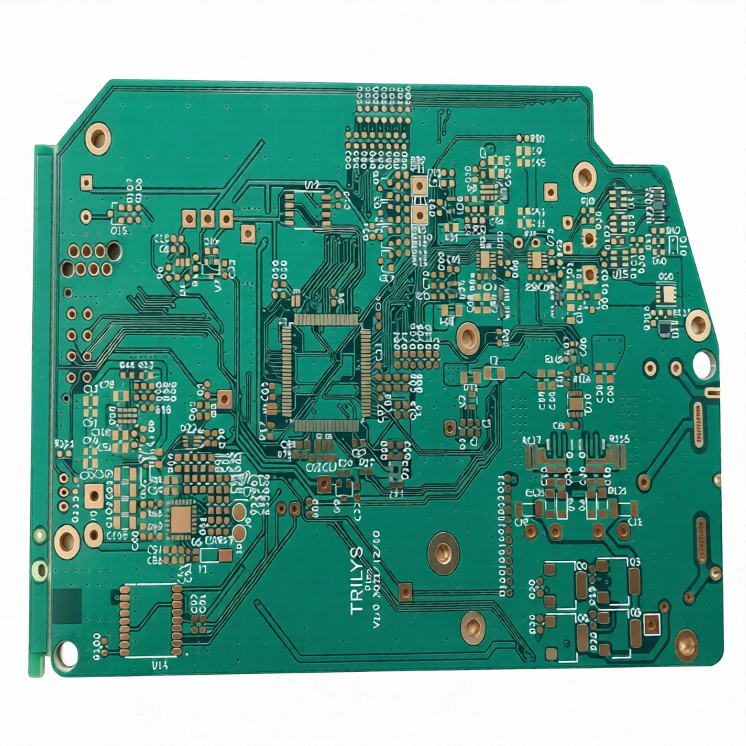
For industrial OEMs, source high-performance bare boards with 1-36 layer capacity. A reliable PCBA manufacturer for complex circuit boards up to 6oz copper.
View productthe board accepts thermocouples in types j, k, t, e, n, r, s and b; rtds pt100 and pt1000 in 2-wire, 3-wire and 4-wire configurations; analog voltage at 0–5 v and 0–10 v; and analog current at 4–20 ma and 0–20 ma. input resolution is 0.1 °c / 0.1 °f, and measurement accuracy is stated as ±(0.2% of reading + 1 °c) or better depending on sensor type.
the relay output gives you 1–2 channels rated 5 a @ 250 vac (spdt) and switches a load directly, which suits a heater rod or fan that is not cycled constantly. the ssr driver gives 1–2 channels with a 12 vdc / 24 vdc output signal and is used where an external solid-state relay handles frequent switching. if your heater is switched continuously, the ssr driver path is the more suitable option.
the analog output is a single channel at 4–20 ma or 0–10 v, described on the product page for proportional valve control and similar modulating devices. relay, ssr driver, analog and logic outputs are all listed as configurable output options, so the mix is part of the configuration you specify. confirm the exact combination you need when requesting a quote.
choose 12–24 vdc ±10% when the board shares a dc rail with other control electronics, or 85–264 vac 50/60 hz when the controller is powered directly from the line. the supply range depends on the model, and typical power consumption is under 5 w.
the stated measurement accuracy is ±(0.2% of reading + 1 °c) or better, depending on the sensor type in use, with an input resolution of 0.1 °c / 0.1 °f. final performance depends on the probe you pair with the board and how it is wired.
channel count and the mix across relay, ssr driver, analog and logic outputs are the main configuration levers, along with the board stack parameters listed on the product page (fr4, 1.6 mm, 2l, 1 oz copper, hasl). the manufacturing path runs from prototype development through low-volume pcb assembly to larger-scale pcb manufacturing services. send the four configuration fields through the quote form or email r.shieh@vortixion.com, and lead time and pricing will be confirmed for your specific configuration.
