
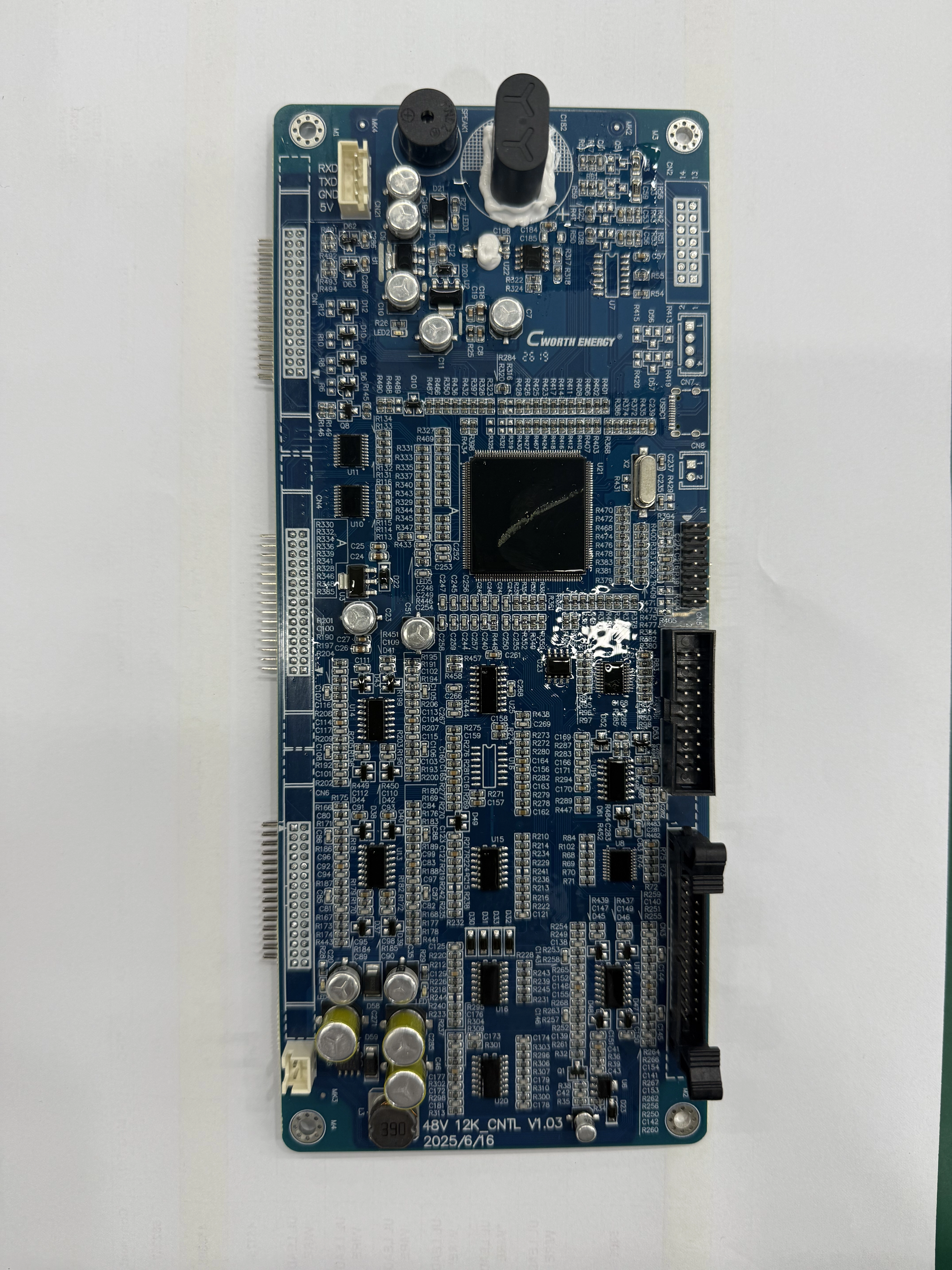
Control Board for Inverter
Co-development of Inverter Control BoardOur team has spent six months cooperating closely with our valued client to jointly develop a brand-new inverter control board. We encountered countless tough…
View productThe reference board on this page is a compact two-layer module built around integrated GPS and cellular antennas, a Li-ion pack with charging circuit and basic motion detection — a practical starting point when you are scoping a custom PCB for pet tracker hardware. Read it as a decision path rather than a datasheet: each section names the choice, the cost it drives and the question to settle before you brief a pet tracker PCBA manufacturer on tooling, test and a volume build.
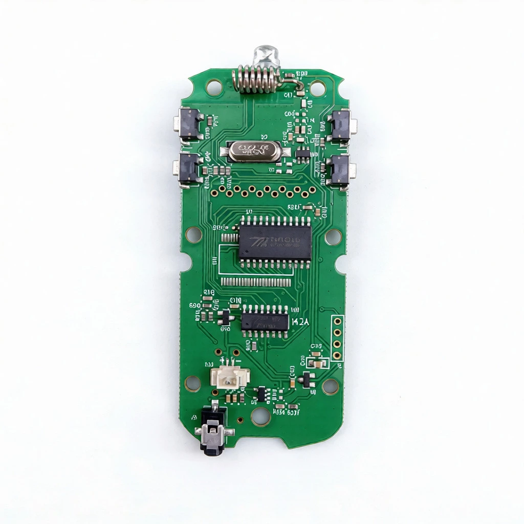
A pet tracker board carries the whole electronics stack of a wearable tag on one substrate: a location engine, a radio link, an energy store and the charging path, all inside a footprint small enough to hang from a collar. Everything further down this page is a decision made against the baseline below.
| Board material | FR4 |
|---|---|
| Layer count | 2L — two-layer |
| Board thickness | 1.0 mm |
| Copper thickness | 1 oz |
| Process / surface finish | HASL |
| Layout options | Single-sided or double-sided |
| Integrated antennas | Cellular and GPS |
| Battery support | Li-ion battery with charging circuit integration |
| Motion sensing | Basic activity and motion detection, with no extra sensors |
| Power design goal | Low power consumption to maximise battery life in a portable device |
| Form factor | Compact layout that places battery and antennas within a minimal footprint; described as a waterproof-sealed, ruggedised build for enclosure assembly |
| Customisation | Modular approach supporting adaptation to custom requirements |
Two layers is not a compromise on this board — it is the reference configuration: FR4, 1.0 mm thick, 1 oz copper, HASL finish, with a compact single-sided or double-sided layout. The question is whether your added requirements still land inside that envelope.
Both antennas are integrated on the board, and the layout is optimised to place the antennas and the Li-ion pack inside a minimal footprint. That is efficient — and it means the antenna area is a fixed constraint once the enclosure is tooled. Move the board 2 mm inside the housing and you can change the lock behaviour without changing a single component.
Treat the keep-out as a drawing you approve, not a note you inherit. Ask for the antenna zones marked on the board outline, then lay the battery, the collar mount and any metal hardware around them before tooling starts.
Buyer decision: approve the antenna placement drawing together with the enclosure drawing, in the same review.
The board is designed for low power consumption to maximise battery life in a portable device, and it supports a Li-ion battery with charging circuit integration. What the specification does not publish is a current figure — so the runtime conversation is one you have with measurements, not adjectives.
| Power decision | What it changes | What to confirm before the build |
|---|---|---|
| Location fix interval | The dominant share of average current draw across a day | How many fixes per day the product genuinely needs versus how many it can afford |
| Cellular reporting interval | Burst current during a report against the sleep floor between reports | The measured peak current, so the pack and the charging circuit are sized to it |
| Sleep current | How much runtime is left when the tag is doing nothing at all | A measured sleep figure, not only the low-power design goal |
| Charging path | Where the connector and charging circuit sit, and how much board area they claim | Connector polarity, placement and the clearance the housing gives it |
| Pack size against footprint | Runtime versus the compact layout the board was optimised for | Pack dimensions agreed alongside the enclosure, not after it |
Buyer decision: ask for measured sleep and peak current alongside the quote. Runtime claims that are not backed by a measurement become a support problem after the first production run.
The board is described as a ruggedised, waterproof-sealed build suitable for enclosure assembly. Three mechanical details decide whether that description survives contact with your housing.
A thin substrate buys vertical room inside a slim tag, but it sets the standoff height and the stiffness the enclosure has to provide.
Confirm the 1.0 mm thickness against your standoffs before the housing is tooled.
Sealing happens at the enclosure and the board interface together: gasket land, connector opening and the antenna edge all sit in the same review.
Test the seal on assembled samples, not on bare boards.
A tag that hangs from a collar sees shock and flex that a bench prototype never shows. The mounting point and the board outline need to agree.
Agree the mounting datum with the sealing drawing in one pass.
The board stays the same 2-layer FR4 design. The manufacturing conversation does not. The board is offered alongside PCB contract manufacturing, high-volume PCBA and EMS services, so the volume step is a scope discussion rather than a new supplier search.
Run this list before you approve tooling. Each item is a build decision hidden inside a drawing.
The board is positioned as a reference platform for prototype validation across cellular and GPS signal integration, power management and waterproof testing. Those four checks are also the four cheapest places to find a problem.
Verify the position fix with the board inside the assembled housing, with the battery fitted and the collar mount in place.
Decision: does the antenna keep-out survive the real enclosure, or does it need to move?
Check the radio link with the housing closed. An open-board test tells you nothing about the sealed product.
Decision: is the antenna placement signed off against the enclosure drawing?
Log sleep and peak current across a full charge cycle with the charging circuit in use, so the low-power design goal becomes a figure you can quote to your own customers.
Decision: does the pack size still meet the runtime promise?
The board is described as a waterproof-sealed, ruggedised build for enclosure assembly. Validate the seal at enclosure level on assembled samples.
Decision: does the housing pass before tooling, not after?
Four common starting points, and the board configuration each one points to on this reference design.
| Your situation | Configuration that fits | Buyer decision to close first |
|---|---|---|
| Pilot tag for a smart-collar startup | 2-layer FR4 at 1.0 mm, single-sided layout, integrated GPS and cellular antennas, Li-ion with charging circuit, basic motion detection | Approve the antenna drawing and run sealing tests on assembled samples |
| Runtime is the headline feature | The same 2-layer board with a disciplined fix and reporting schedule and a pack sized to the housing | Get measured sleep and peak current before publishing a runtime claim |
| The product needs sensing beyond motion | The standard board does location and basic motion with no extra sensors; additional sensing is a custom adaptation | Define the sensor set, then check whether the 2-layer envelope still holds |
| Programme is heading to retail volume | Same stackup quoted with fixture-based functional test and agreed change control | Settle panelisation, consignment and test scope in the first quote |
This reference board is quoted, not checked out — there is no cart on the site. Send the inputs below and the stackup, assembly and test scope can be priced together.
Start from the reference specification — 2L FR4, 1.0 mm, 1 oz copper, HASL, integrated GPS and cellular antennas, Li-ion with charging circuit — then tell us what your product changes.
r.shieh@vortixion.comKeep adjacent product options together for a faster catalog comparison.
Co-development of Inverter Control BoardOur team has spent six months cooperating closely with our valued client to jointly develop a brand-new inverter control board. We encountered countless tough…
View product
Flexible PCB board solutions for dynamic applications. Our flexible pcb manufacturing provides high-density routing and reliable pcb assembly services.
View product
For industrial OEMs, source high-performance bare boards with 1-36 layer capacity. A reliable PCBA manufacturer for complex circuit boards up to 6oz copper.
View productthe board is built on fr4 with a 2-layer stackup, 1.0 mm thickness, 1 oz copper, and a hasl surface finish. the layout can be single-sided or double-sided.
yes. the board includes integrated gps and cellular antennas, and the layout is optimized to place the antennas and the li-ion battery within a minimal footprint.
the design supports a li-ion battery with charging circuit integration and is built for low power consumption to maximize battery life in portable devices.
it supports basic activity and motion detection. the product information describes the sensing scope as location and basic motion with no extra sensors.
the product is described as a waterproof sealing and ruggedized form factor suitable for enclosure assembly. sealing and waterproof testing should be validated on assembled samples.
the board uses a modular approach that supports adaptation to custom requirements. it is also offered alongside pcb contract manufacturing, high-volume pcba, and ems services.
